jueves, 27 de septiembre de 2012
martes, 25 de septiembre de 2012


domingo, 23 de septiembre de 2012

martes, 18 de septiembre de 2012
Foldinator Origami Modeler and Diagrammer
Abstract:
Foldinator is a software application for visualizing objects made by the sequential folding of flat sheet materials, and for generating annotated documents that record and display the sequence of steps in the object's creation, providing a useful set of instructions to others. Such sequences can be used to represent origami models, packaging items, displays, and many other products. In contrast to a generic 2D drawing or 3D CAD program, Foldinator models the special qualities of sheet material, particularly its geometric configuration with respect to the constraints of manipulating 2D materials in 3D space, and also its thickness, flexibility and other properties. Foldinator contains an object model for the sheet material and its geometric state, eliminating tedious redundancy on the part of the author trying to express such an object without the benefit of such a model, and allowing him or her to conduct simulations of the object under continual deformation.Background:
The goal of this project is to create Foldinator as a tool for intuitively exploring origami folding and documenting origami models in a sharable format. The initial version of the Foldinator will allow the sharing and display of documents over the World Wide Web, and will have a downloadable authoring tool for creating Foldinator origami models and documents. Future versions of the Foldinator will feature high-resolution graphic output suitable for print publication. I intend to make Foldinator publicly available as a shareware application to serve as a resource to the origami community and promote online sharing of origami models.I am a software designer and developer, and a longtime paper folder. I see the Foldinator as an interesting development project and interface design problem. The idea of representing an origami simulation in an engaging, intuitive interface has a certain appeal, and the application of diagramming lends the effort some utility. I initially came up against the problem of origami diagramming several years ago, while preparing a set of model instructions for publication. My solution in 1994 was hand drawing, which seemed to be the best option given my resources at the time. However, it had a number of obvious drawbacks, not the least of which was the trouble of converting the diagrams into a format suitable for electronic distribution.
The Foldinator project arose as a response to this problem. I have been pursuing Foldinator since mid-year of 2000, at first mainly conceptually, by working out an approach to the application design. I have been developing the software since the fall of 2000.
Motivation:
Making origami diagrams the old-fashioned way is hard. It requires specialized tools and skills, and is a complicated, tedious process, especially for complicated models. Since it involves a lot of repetition and minute variations, it seems like a good candidate for an automated, computerized approach.Currently, someone wishing to use a computer to assist them in creating origami diagrams has several options to choose from among available software packages. One class of these is 2D drawing and illustration programs such as Illustrator, Freehand, CorelDraw, and their ilk. These programs, however, while removing some of the tedium by allowing the author to copy and paste, still have their drawbacks. The main shortcoming is the lack of a geometric or other kind of model for the paper and the operations performed. The author is required to manually construct all of this information in his representation, and at a level that simply emulates the appearance but not the underlying structure.
Another alternative is to use a 3D modeling and animation package such as AutoCAD, Mathematica, or 3D Studio Max. These tools, while allowing the author to create a model representing the origami, have drawbacks of their own. Firstly, these software packages tend to be expensive and complicated, requiring specialized skills to use and long experience to master. Also, the modeling systems they employ are generalized, not specific to paper and its properties, so many of the capabilities of the software are extraneous to the task at hand. Further, the 3D renderers used in these packages are not designed for origami models, although it would be possible to create appropriate render settings. To use a package like this for this task is probably overkill; one could spend a lot of time customizing the environment to be suited for this application, but there are many features one does not need that have to be dealt with.
My solution to this situation was to develop a custom application for modeling origami. Origami is a formal system and therefore well suited for software representation, and creating diagrams is a good application for an authoring tool or expert system. The geometry of paper obeys a relatively small set of well understood constraints. And similarly, the vocabulary of paperfolding includes a small set of operations, each of which can be represented in a computer simulation. The depth of the experience comes from the ability to repeat operations ad infinitum and to choose what operation to apply next every step of the way. Indeed, the same qualities that make origami an elegant, aesthetic and appealing art form in the real world are the ones that make it an interesting process to program as a computer simulation. Indeed, working on the development of Foldinator has deepened my understanding of origami, and caused me to rigorously formalize many of my intuitive notions about the properties, geometry, and behavior of folded paper.
Some Known Prior Work:
When I began to consider developing the Foldinator, I searched for previous work done in the field. To my surprise, there was relatively little. Indeed, one of primary motivations for delivering this paper at 3OSME was to see if I could learn about other’s work in this area.Currently some origami books feature computer-generated diagrams, but many books still feature hand drawings. Sometimes these are very nuanced and beautiful; sometimes not. Additionally, origami diagrams are available on the World Wide Web, either downloadable, or viewable in the browser. These, however, tend to be simple static image or text/image formats such as html pages, .JPEG or .GIF images, or .PDFs. They vary greatly in quality and image resolution. And, as with their print counterparts, these documents have been laboriously hand-crafted.
John Montroll and Robert J. Lang seem to have some software expressly for modeling and diagramming origami. In their book Origami Sea Life (1990) I found this reference on page 256: "additional software used in the production of this book was written by Robert J. Lang". I spoke to Mr. Lang at 3SOME conference about this, and apparently he has been experimenting for a long time with various bits of software for origami diagramming, but to my knowledge has not published the software itself or any papers on it.
The only other prior art I was able to uncover was from the Wolfram Mathematica web site. Lucy Zamiatina has developed origami simulations in Mathematica (http://www.wolfram.com/products/mathematica/experience/its.html). This project seems to have been devoted exclusively to modeling and did not address issues of diagramming or rendering.
Design Goals of Foldinator:
In starting any software development project, is important to enumerate the design goals. The Foldinator has three primary design goals:- Users can model an origami model on a computer,
- Users save out annotated steps to generate diagrams to share with others, and
- Users interact with an intuitive UI based on traditional origami symbols to manipulate the model.
The Development Platform
I am developing Foldinator using a combination of Macromedia Director and Macromedia Flash. There are a number of reasons for this. Director, which is the main development environment, is very well suited for building interactive User Interfaces, and for rapid prototyping. It has high-level structures to represent and manage collections of visual and data objects, and includes an object-oriented programming language, Lingo, that is well suited for representing model and geometry. Additionally, Director has a powerful graphics management and display engine, which greatly simplifies the task of programming the visual display of the interface and of rendering the origami model.Director also is advantageous in that it encapsulates Flash objects. Flash is designed for the flexible display and animation of resolution-independent vector-based graphic objects. Flash elements can be freely scaled, rotated, distorted and otherwise manipulated without loss of resolution and without introducing visual artifacts. Many of the UI objects in the Foldinator, and many of the 2D primitives that are used as components of the 3D model, are created in Flash and imported into Director.
Another important factor in my choice of development environment is that the resulting application will be available to the widest possible user base. The Foldinator authoring tool will be a downloadable application program available for both the PC and Macintosh platforms; Director makes cross-platform development very simple. The Foldinatordocument viewer will run inside any modern web browser as a Shockwave document. Foldinator origami model documents will be based on the .TXT format and accessible to both authors and viewers on any platform.
The Object Representation:
At the heart of the Foldinator application is an object called Paper. Paper begins its life in a new Foldinator document as an unfolded square of paper with two sides and (nominally) zero thickness. When the user creates a fold, the crease divides the square polygon into two smaller polygons joined with a common, hinged edge. As the model progresses in its development, new folds propagate thru multiple layers of paper, creating numerous new polygons in the model, according to the kind of fold. The details of this are managed automatically by the software.Clarity of display for the origami model necessitates variation from "true" 3D projection. Rather, aligned layers of paper are shown systematically offset so that the viewer can read the diagram. This requires modification of the 3D engine to create the projection from the modeler to the renderer. See Figure 1 for an example of this projection applied to the Preliminary Fold.
Also, special attention was given to lines and line weights in the development of the model view. The language of origami diagramming requires subtle and meaningful distinctions between various kinds of lines, such as creases and edges, and the various kinds of dashed and dotted lines. In this regard the use of Flash has paid off handsomely.
Figure 1: Projection and rendering of a model.
The next higher level of object is the Scene. The Scene contains the Paper model, plus diagramming symbols such as arrows and dashed lines, as well as text annotations. The Scene is a composite 2D/3D object.
The Sequence contains a series of Scenes and represents the origami model as a work in progress or as the completed set of folding instructions. It also includes global annotations such as title, author, copyright information, and special instructions for folding the model that don’t fall in a particular step.
A Sequence can be saved or loaded as a file. This is a Foldinator document. Currently the Sequence is encoded as a .TXT file. Rendered scenes are encoded as .BMP or .JPG files, and are referenced by the .TXT file. Support for .EPS or similar print-resolution images is planned for a future version of the Foldinator.
The User Interface:
Now it’s time for a guided tour of what the Foldinator application will look like. There are three principal views of the origami model. These are: the Main View, the Map View and the Section View. Additionally, there is a Sequence View that provides a high level view of a series of diagram in thumbnail format. Within each view are various controls, tools, and other UI elements.The Main View is, perhaps obviously, the main view where the author works on his origami creation. It is designed to look and act as much like as an origami model as possible. It is manipulable and annotatatable. See Figure 2 for an illustration of a model in the Main View.
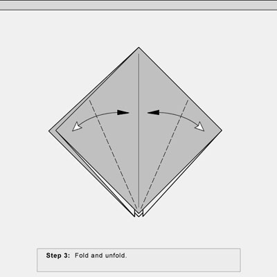
Figure 2: Main View
The Map View shows flat paper with all the folds in place. This is sometimes called the fold pattern. See Figure 3 for an illustration of a model in the Map View.
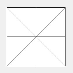
Figure 3: Map View
The Section View displays a cross-section thru model to show the arrangement of the various layers of paper. The line of the section can be set in the Main View. See Figure 4 for an illustration of a model in the Section View.
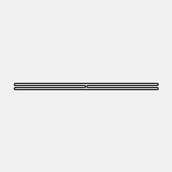
Figure 4: Section View
The Sequence View shows a series of thumbnails of the folding steps. The user may use this to step thru his model sequentially. See Figure 5 for an illustration of a model in the Sequence View.
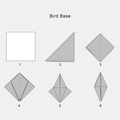
Figure 5: Sequence View
Using Foldinator:
Figure 6 shows the initial view of a new Foldinator document with the paper in the center of the screen and the various controls arrayed around it. This figure is taken from an early prototype version, so all of the controls are not fully fleshed out in detail. However, all of the main components are in place. At the top of the window is the Menu Bar, where the user can access various file- and application-level commands. On the left side is the Tool Palette, where the user can access the tools to work on the origami model. These tools use the icons of traditional origami notation, so their functions should be apparent to anyone familiar with reading origami diagrams. The use of some of the tools is detailed below. At the center bottom of the window is the Annotation Space, where the user can type in text instructions to accompany the symbolic markup of the step. Finally, at the lower right is located the Step Controls, which allow the user to execute the current step and move ahead to the next one, and also to move backward and forward thru the sequence of steps.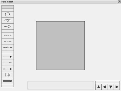
Figure 6: A new Foldinator document
Usually the first thing a user will want to do when creating a model is set the Paper Properties. Access to this functionality is provided thru the Menu Bar or by right-clicking on the Paper itself. Paper properties include the shape or aspect ratio of the paper, as well as its color or graphic pattern, and its thickness. The default values for paper shape and color are: a square sheet with one white side and one side colored gray. As for other physical characteristics of the paper, currently "ideal" paper is the only representation supported. Ideal paper has zero thickness (although it cannot pass through itself or do other "impossible" things), absolute stiffness, always produces precise and permanent creases, and cannot be stretched, curved, cut or torn, only folded.
The top three tools on the Tool Palette are to Rotate, Flip, and Zoom the model. I implemented these functions first to test the basic integrity of the code that controls the 3D model and its projection into the rendering space, and the code that links user actions to the manipulation of the 3D model.
Making a Fold:
Figures 7 thru 10 illustrate the process of making a fold and executing a step in the Foldinator. To begin, the user selects the type of fold. Currently the available choices are Valley Fold, Mountain Fold, and Reverse fold. Support for more complex folds, such as Petal Fold, Squash, Rabbit Ear and Sink are planned, but most of these can be accomplished by sequences of simpler folds.Figure 7 shows a Valley Fold selected and the user placing the fold by dragging a line. Foldinator supports Snap To by default, although it can be turned off. Most origami folds, especially at the beginning of the model, are placed relative to existing features of the geometry of the paper. The user can easily place a fold at the bisector of two existing lines, such as parallel or adjacent edges of the paper, or an edge and an existing crease, or two existing creases. The user can also snap to a point at the intersection of any pair of creases or the intersection of a crease and an edge, both for locating the end point of a crease or for locating the destination of a locatable point on a folded flap.
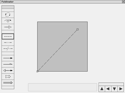
Figure 7: Dragging a line to make a fold
In Figure 8, the fold has been located, and now the direction of the arrow must be specified, that is, the user must indicate whether the lower right corner is to be folded up to the top left, or vice versa. When the second end point of the fold is placed, the arrow automatically appears, with the arrow head on whichever side of the line that the mouse happens to be. To change the direction of the arrow, the user simply drags the mouse across the line and clicks. The example illustrates an arrow of the type Fold, although the user can change the arrow to other types including Unfoldand Fold and Unfold.
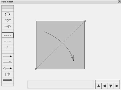
Figure 8: Orienting the arrow
Once the fold is placed, the user may annotate the step, as shown in Figure 9. This is accomplished simply by clicking in the annotation field and typing. Sequential labels (e.g. "Step 1") are provided by default.

Figure 9: Annotating the step
All that remains is to execute the step using the Step Controls in the lower right of the application. This is shown in Figure 10. When the user clicks on the "Next" icon, the model animates the action specified (in this case, a valley fold across the diagonal of the paper), and updates its internal state so as to be ready for the user to create the next step. Additionally, the Step Controls allow the user to pop up from the various Scene Views (Main, Map, and Section) to the Sequence view, to step down from the Sequence View into the Scene View, and to move backward or forward thru the various steps in the model sequence.
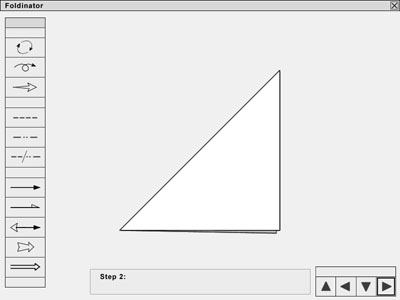
Figure 10: Executing the step
Foldinator also contains global document controls to allow the user to create new documents, open and save existing documents, and perform related functions. These are provided thru the Menu Bar.
Issues:
There are a number of issues that emerged as the development of the Foldinator proceeded. First among these is the look and feel of the application, which is very important to me. I felt very strongly that the lines should appear smooth and free of aliasing artifacts, and spent a considerable amount of time arriving at a solution to this problem. Similarly, I put a lot of effort into developing a projection from the 3D model to the 2D image that would elucidate the features of the model that were important to its representation for folders. Choices for the development platform and the way in which I structured the code representation of the origami model emerged as a result of these priorities.Some aspects of simulating an origami model appear to be difficult to implement, and I am deferring them until a future version of the Foldinator. I would very much like to support curvature in folds and in the paper itself. Many of the origami models I currently make that I would like to document feature a sculptural, curved approach in the finishing stages of the model. However, this will require me to introduce splines to the 3D model, which is currently based on polygons, and will require a reworking of significant amounts of code. Luckily, Macromedia has just released version 8.5 of Director, which includes mesh-based 3D geometry objects as part of an extensive new feature set to support 3D animation as an integral part of the Director environment, so I will be investigating converting my 3D engine to Director 8.5 in the near future.
Another potential issue has to do with the complexity of elaborate origami models in 3D. As it is still under development, I have not yet tested the Foldinator with very complex models as of yet. While I believe that the constraints I have implemented are sufficient to prevent the paper from folding thru itself or doing other "impossible" things, I have not proven in a rigorous mathematical sense that this is in fact the case. Also, I can envision a user folding a model so complex that at some point my projection produces an image which fails to achieve the visual clarity I am aiming for.
Finally, there is the issue of screen resolution vs. print resolution. Currently, all of the image projection and rendering functions are designed to display to the screen. While in principle, the Flash primitives that compose the images are resolution-independent, I have not yet implemented or tested the exporting the images at high resolution to a printable format.
Current Status and Future Goals:
Foldinator is currently under development by Zing Man Productions. (Please note: the features described in this paper do not constitute a formal specification, and may change in the final release version.)If public response to Foldinator 1.0 is sufficiently positive, I will continue to add features to create a more sophisticated version of the software. Planned features include: support for paper with non-zero thickness and other variable physical qualities, for paper of arbitrary non-rectangular shape, support for curved folds and curved paper, support for images to be mapped onto the paper as a texture map, and for print-quality rendering of the steps. I would also like to add support for multiple sheets of paper in a scene for creating geometrics and other compound origami models. Further, I am eventually planning on expanding the tool palette to support non-folding operations such as the ability to specify cuts, holes, tabs, slots, glue, staples and rivets to support generic sheet material fabrication.
Based on the initial feedback I have gathered from fellow origami enthusiasts, I expect that the Foldinator will fill a useful role in the community of paper folders who wish to share their creations with one another. I look forward to its completion and public release.
References:
Origami for the Enthusiast, John Montroll, 1979 Dover PublicationsOrigami for the Connoisseur, Kasahara and Takahama, 1987 Japan Publications
Origami from Angelfish to Zen, Peter Engel, 1989, Dover Publications
Origami Sea Life, John Montroll and Robert J. Lang, 1990 Dover Publications
Contact Info:
John SzingerZing Man Productions
http://www.zingman.com
Origami Diagramming Conventions, Robert Lang


Origami Diagramming Conventions, Part I
These articles were written in 1989–1991. Despite many changes in the origami world over the following decades, the recommendations remain basically sound. I've updated a few bits with some footnotes.
Origami is an international phenomenon that has moved far beyond its traditional boundaries of Japan and Spain. Its practitioners are found world-wide, and the language they communicate in is made up of diagrams. The great strength of this language is its uniformity across the world. In this series, based on a panel discussion at Convention '88 and a diagramming questionnaire sent to diagrammers around the world, I am recognizing existing standards of diagramming and proposing new ones to further promote worldwide communication of the art.[1]
Introduction
One of the difficulties facing a diagrammer is that of consistency with the past, his local folding group, the national scene, and potential co-authors. In the case of The Friends[2], there is also the question of consistency with what has been printed before in convention programs, teaching sessions, and other articles in the Friends' Newsletter (such as David Shall's concurrent series of articles). Minor differences appear, for example, in symbols lists printed in the Friends' Newsletter#27 (Fall of '87) and the Annual Convention '88 program (Spring of '88). When you bring in books, the situation gets even more complicated. I have written, or am working on diagrams for, three different books, two with a co-author. Because we each had strong opinions about what symbols were best, we ended up compromising, and I must use a different set of symbols for each project. As confusing as this is for a diagrammer, it is bound to be worse for the reader.[3]
Before Convention '88, a number of folders recognized that there was a need for standardization, and The Friends have taken steps toward that end, for example, publishing the lists just mentioned. Before the convention, I sent a questionnaire to some 25 diagrammers around the world; many returned not only the questionnaire but sent pages of additional comments. At the convention itself, we held a panel discussion on uniformity that included most of the American diagrammers and some overseas participants as well. Its results, and the results of the questionnaire, will be included in the articles that follow.
This article kicks off a series in which I will take a detailed look at diagramming symbols and conventions. Where there have been competing claims, I hope to resolve them. Where there are gaps, I hope to fill them in. I also will give some explanation for why to use a certain symbol. This series will run as long as it takes to cover the material, so if you have strong disagreement with something here, send me a letter and I'll discuss it in a future installment.
It would be nice to start with something simple, like a valley fold. We're going to start even simpler than that. Many of the comments on symbology that I received concerned generalities rather than specifics; they took the form of basic principles to follow when diagramming a model. Let us begin with some of those principles. Following these ideas will eliminate many of the bugaboos that have had readers tearing their hair out, and they can help to resolve future questions of propriety in diagramming as they arise.
Be consistent with the past
The way things have been done in the past has a big thing going for it: it is known to work, and it is known to many. In origami diagramming, that means that unless there is pressing reason otherwise, we should use the standard notation developed by Yoshizawa. To fully appreciate the change his symbols made in the world of folding, one has only to examine some of the older Japanese books with their dashes and P's, or the modern German books with no arrows and no distinction between mountain and valley folds. Yoshizawa's notation is clear, it has stood the test of time, and therefore it should be the diagrammer's first source. (Just what those symbols are will be shown later—these are general principles at the moment.)
Yoshizawa is not the ultimate authority, though, because he does not diagram complicated models, and his symbols are therefore somewhat limited. Many of the newer symbols, and most of the contentious ones, were developed more recently to describe sequences that are not easily described by the standard symbols. It would be unreasonable for the diagrammer, when confronted with an entirely new sequence, to try to squeeze it into the existing symbols. And it would probably be equally uncomfortable for the reader to follow. However, other authors have stepped in to fill the gaps in origami symbology. In the West, books by Harbin, Randlett, Sakoda, Kenneway, Montroll, Weiss, and Jackson, already describe a multitude of sequences. Many of these books are, unfortunately, out of print, but they are still used as a reference by many folders. Those that are out of print may be found in the libraries of the major origami societies, and models from them continue to resurface in the periodicals and publications of the major origami societies, so they are still accessible. Consequently, if Yoshizawa doesn't have a symbol for it, one of these probably will.
This is not to say that you should never replace an old symbol with a new one—because in a very few cases, that is exactly what I plan to suggest—but if you do, you had better have an overwhelmingly good reason for it. For example, it was suggested at the panel discussion that dashes and dot-dot-dashes for valley and mountain folds should be replaced by dots and dashes, respectively, because they were easier for the reader to distinguish. Even if that were so (and I'm not saying it isn't), the dashes and dot-dot-dashes are so firmly entrenched in the minds of folders that making a changeover would bring mass confusion to those already familiar with the art. So dashes and dot-dot-dashes will remain.[4] (We won't mention dot-dashes versus dot-dot-dashes yet). On the other hand, the Harbin "repeat arrow" is less well established. It is avoided by several prominent authors (Randlett, Weiss/Jackson, Montroll), has several shortcomings, and I am going to suggest a replacement for it later on.
What I've done here is to collect from various sources symbols and drawing conventions that are general, clear, and consistent with the past. I would like to think that the symbols in this series could describe any situation that would ever arise, but I'm not that naive. Origami is developing technically at an ever-increasing rate, and the art will almost certainly outstrip the capabilities of any description language. Someday, a new procedure will arise that cannot be easily diagrammed using the standard notation. However, if you are diagramming a step, you should first try to use the symbols shown here; and only if that is impossible or unreasonably difficult should you make up new ones. And even then, keep simplicity, generality, and clarity uppermost in your mind.
Make the drawings stand alone
The goal of international origami communication can only be reached if anyone can read directions; therefore, a set of drawings should not have to rely on language. Drawings should indicate all relevant information. Verbal instructions should not be necessary to resolve ambiguities.
Make the text stand alone, if possible
Because many people work better from verbal descriptions than from diagrams, the diagrammer should, if possible, include verbal directions sufficient in themselves to work through the model. However, it is nearly impossible to meet this goal in complicated models. The verbal constructions required simply to navigate around the model become daunting, and it is flatly impossible to describe solely in words a step in which you bring twenty or thirty creases together (as often happens in box-pleated models). In such cases, the verbal directions can still enhance the clarity of the drawings but it would be impractical to strive for complete self-sufficiency. In general, though, beginners rely more heavily on the words than experienced folders, so it is more important to get the words right on easy folds than on hard ones.
Use letters to indicate important features.
It is astonishing to note the amount of simplification that can come simply by sticking a single letter on the drawing to indicate a point or flap. Compare "Fold the large bluntish point just left of the center line of the model up to the point where the crease made in step 4 crosses the edge of the squash-folded rabbit ear under the right lobe of the large, irregular portion of the model" to "Fold flap A to point C." On simple models that have words, the beginner has a tendency to follow only the words and not look at the picture except as a last resort. The occasional reference to a letter on the figure has the helpful effect of reminding such a person to look occasionally at what the drawing is doing.
Be grammatically correct
Striving for a clear and unambiguous verbal description means, among other things, that you must stick to a consistent origami grammar. It is well-established in English-language origami books (e.g., the Harbin/Randlett books) that origami nouns are not hyphenated, but verbs are. Thus, I reverse-fold the flap into the interior, but I flatten out the reverse fold. Is that a double rabbit ear? It was, but I triple-petal-folded it a few minutes ago.
Similarly, while the names of different moves are nouns and should thus be in lower case, those that incorporate names, such as Elias-stretch (verb) or Elias stretch (noun) should have the name capitalized. The names of bases, on the other hand, are proper names, and should be entirely capitalized: Bird Base, Waterbomb Base, Preliminary Base. (Okay, Preliminary Fold.) Whether you capitalize the name of the final model is up to you. If it is simply a description ("This is a bear."), it should be lower case. If it is a title ("Man Riding a Unicycle at Dusk"), it should probably be capitalized.
Use arrows to indicate motion

Figure 1. Use a leader to indicate information about the model. Use an arrow to indicate motion or action.
An arrow should be used only to indicate motion or action: movement of a flap, pressing here, squeezing there, pulling this, et cetera. Specifically, it should not be used to point out a particular feature or to convey factual information (see figure 1). In older origami books (Origami Dokuhon, for one) you will find a different type of indicator; it is called a leader, and consists of a very thin line extending from the information to the drawing. Leaders are used widely in mechanical drawing. They should be used in origami as well.
Don't leave the reader dangling

Figure 2. What happened? Show results before turning the paper over.
One of the greatest cruelties a diagrammer can perpetrate upon the reader is illustrated by the following scenario. In step 113, we are instructed to perform an exceedingly complicated series of closed sinks and to turn the paper over. Step 114, therefore, shows the opposite side of the model. The paper does not get turned back over until step 243, at which point we discover we folded step 113 all wrong, but it's too late now.Always show the result of any procedure immediately.
This seems like an easy scenario to avoid, but there is actually a very good reason why it happens all the time. Drawing diagrams is tedious and hard work, and it seems like a great waste of time to draw a step in which nothing happens. The diagrammer must realize, however, that his goal is to make things as easy as possible for the reader, not for himself (painful though that may be).[5]
Show one step per drawing
For much the same reason, it is common practice to cram as many steps into each drawing as is possible. This is not only confusing to the novice, it is not the way anyone actually folds a model. Suppose you are folding an animal with four legs and a head. You don't make one fold on the front legs, one on the back, one on the head, another on the front, another on the back, another on the head, a third on the front, a third on the back, a third on the head, and so forth. The way most people would fold the animal is to entirely fold the front legs, then entirely fold the back ones, then turn attention to the head (or some similar permutation). If people don't fold a model in a particular order, it shouldn't be diagrammed in that order. The only reason to cram many procedures into a single step is to cut down on the amount of drawing; but again, that is a case of the diagrammer placing himself ahead of the reader, and that is not the proper state of affairs.
Distort the model for clarity

Figure 3. (A) is more accurate, but (B) is more informative.
If a diagrammer were to draw a model in a mathematically ideal way, it would convey very little information: all edges would line up, all creases would run all the way to corners; multiple layers would perfectly overlap. In practice, then, the diagrammer must introduce small distortions: gaps between edges, layers that do not line up. Such distortions convey far more information and should be included wherever appropriate (of course, they are also harder to draw).
Along those same lines...
Show multiple layers whenever possible
Here is where many diagrammers fall down on the job: if a model has multiple edges stacked up on each other, SHOW the multiple edges. If there are too many, you don't have to show them all, but at least show enough to indicate that there's more than one layer there. This is far more illuminating to the reader than a mathematically exact silhouette of the model.
And now, having established those basic ideas, on to some symbols.
[1] These articles were written in 1989–1991. I've updated a few bits with these footnotes.
[2] The Friends of the Origami Center of America, which is now called OrigamiUSA.
[3] The next three books were solo efforts, and I've pretty much standardized on the consensus symbols described here, as has a large part of the origami diagramming community.
[4] However, in large crease patterns (such as the "crease pattern challenges" in Origami Tanteidan Magazine, dashes and dot-dashes blur into incomprehensibility, and use of two contrasting line colors becomes a more useful tool. We should never let history and convention get in the way of clarity.
[5] In the days of pen and ink, the tendency of diagrammers to be sparing with their drawings was understandable (if not necessarily forgivable); but when duplication-and-modification is a matter of a few mouse clicks on a computer, there really is no excuse for not showing the result of every step.
Diagramming, Part II
Lines: edges, creases, mountain and valley folds
In Part I, I wrote of many of the general principles that should guide the origami diagrammer. They may be summarized roughly as, "make it simple," "make it consistent," and "make it thorough." How these principles are actually put into practice will be the topic for the rest of this series. In this installment, I'll talk about the bread and butter of diagramming: lines, mountain folds and valley folds.
There is a fair amount of craftsmanship, if not artistry, in diagramming. At the very least, there are distinctly recognizable styles of diagramming, just as there are distinct styles of folding. In attempting to define the standards of diagramming for maximum clarity, we must avoid squeezing individual expression entirely out of them. Our goal is clarity, not clones. Thus, a small amount of variation between different diagrammers' work is inevitable. However, these variations should be in points of style—line weights, quality, variations in proportions—and not in basic symbols.
Edges versus creases
Professional diagrammers—meaning those few who write books and get paid for it—usually use two different line weights in their drawings to convey edges and creases. Typical sizes are 1- and 1/2-point lines, respectively, for edges and creases. (A "point" is a typographer's unit, equal to about 1/72nd of an inch). Professional diagrammers achieve this by using technical pens—for example, Rapidograph pens. They cost about $15 each, occasionally clog up and, because they are ink pens rather than pencils, the consequences of a mistake are difficult to eradicate (electric erasers cost anywhere from $60–$100). That is how professionals get two different line weights, but most diagrammers are not professionals; they don't have access to professional drawing tools, and they should not be required to use them simply to produce a tolerably readable origami drawing.[6]

Figure 4. Crease lines should not contact the edges that the creases end upon. They do touch edges that they go under.
Multiple line weights, while desirable in origami drawings, are not that important. We may reasonably hold a professional to higher standards than the average folder who is simply sending a model for a convention program. The average folder will be diagramming with a single line weight, and as often as not, using a pencil or ball-point pen. Diagrammers who draw with a single line weight distinguish edges from creases like this: a crease line does not touch the edges at its end. It always has a gap between it and the edge that it ends on. The exception is when a crease line goes under another layer; then, and only then, does it actually contact the edge (see figure 4).
On simpler models, you should draw all visible creases on every step of the model, as this aids the reader to orient himself and the paper. Of course, if the crease is used as a reference point, it should definitely be drawn! As models get more complicated, however, the drawings can become cluttered with extraneous creases (and of course, so can the model). In the interest of clarity, then, unimportant creases may be omitted as they cease to be useful. You should be consistent with omissions, though. A crease line that appears, disappears, and reappears erratically throughout the folding sequence is confusing and should be avoided.
Valley folds

Figure 5. Beginning and ending with a dash, rather than a space, permits a more precise description of a fold. This is especially important when the fold is not what you might expect it to be; in the shape on the left, one might be tempted to fold from corner to corner. In the right drawing, there is no ambiguity: you don't.
In the panel discussion and folding questionnaire I sent out, there was a tremendous variation in what people said were the "standard" or "proper" ways of drawing various folding maneuvers. Thankfully, there was little or no dissention on what constitutes a valley fold. A valley fold is indicated by a dashed line—no ifs, ands, or buts. However, there is plenty of room for variation beyond that! Here is a choice: should a valley fold start and end on a dash or a space?
As you can see from figure 5, beginning and ending with a dash permits a more precise description of the location of the fold (which is, after all, usually determined by its endpoints). Starting and stopping on a dash are especially important if there is not a definite reference point for the fold (as I've purposely done in the figure). There is another reason for adhering to this convention; if a valley-fold doescease without hitting an edge, that will unambiguously indicate an unresolved crease (as in shaping or some precreases). However, if one is using drafting tape with predefined dashes to make dashed lines, then you can usually only get one end of the line to start with a dash. The other lands where it lands, and there is nothing you can do about it.
(The same goes for most computer-aided drawing programs, including the one I used to make the figures for this article. The method I used to get the lines in figure 5 to start and stop on a dash was difficult enough to be impractical for regular use. Therefore, most of the figures illustrating this series will only have one end of the dashed lines aligned.)[7]
But putting in a dashed line for the valley fold is only half the story in conveying the fold. The other half is the arrow. The arrow's importance in communicating a model to the reader cannot be underestimated. This is especially true in drawings for the beginner. Beginners approach folding from diagrams differently from those more experienced in the art. The experienced folder will look at a figure with a dashed line through it and think "Ah, I must make a crease that runs from point A to point B." That is, an experienced folder will think in terms of where the crease must go. Very few beginners approach folding that way. Rather than concentrating on where the crease is to be placed, a beginner wants to bring one point to another and let the crease fall where it may. In this approach, the actual location of the crease is not very important. Therefore, you must show an arrow that indicates clearly the motion that the paper undergoes.

Figure 6. Assorted arrows used for valley folds. (a) Yoshizawa. (b) Randlett. (c) Harbin. (d) Kasahara.
What arrow do we use for a valley fold? There is a lot of variation in arrows in the literature: a sampling is shown here (figure 6). If we were to stick to Yoshizawa, it would be a cleft, filled arrowhead. Because of its unmistakability, however, I prefer the symmetric split-headed arrow used by Randlett and Montroll. However, the exact form is not crucial. It's a point of style. What is crucial is that it besymmetric and that it be either open (as with Randlett) or filled (as with Yoshizawa), but not hollow. This is to distinguish it from mountain fold arrows and others that I will get to.

Figure 7. (a) Typical arrows of motion, arrows that show where the paper moves: Valley fold, mountain fold, and turn the paper over. (b) Typical arrows of action, arrows that indicate an action performed on the paper: Push here (Montroll), pull paper out from here (Weiss/Lang), inflate here (Shall).
In most texts, arrows that indicate motion of the paper have a stem that is a single line, while arrows that indicate an action applied to the paper (e.g., pressure, inflation, and so forth) have a hollow stem (figure 7). This is a good standard to adhere to.

Figure 8. Why cleft-tailed arrows are poor for indicating motion. One the left, the arrow does not indicate clearly whether the reference point at the top is the vertical or the slanted crease. The drawing on the right clearly indicates that the reference point is the intersection of the slanted crease with the top edge.
Additionally, an arrow that indicates motion of the paper should not have a cleft tail (figure 8). It should, in fact, have no extra tail at all (in addition to the stem of the arrow). The tail of an arrow of motion is often as important as the head. While the head may indicate whether to bring the paper toward you or away from you (through its symmetry or asymmetry), the tail indicates precisely the reference point or spot undergoing motion. If you are to bring point A to point B, the tail of the arrow will touch point A and the head point B. Using a cleft tail reduces the precision of the drawing and adds nothing to it.
If there are two reference points that are to be brought together, the tail of the arrow touches one of them while the head touches the other. (Small gaps may be introduced to distinguish the arrow from the paper). If there is no reference point, then the tail should start at the "center of mass" of the moving part and the head should touch the spot where it ends up.
Nearly always, the flap that is undergoing motion in a valley fold is moving out of the plane of the page. To indicate this motion, the path of the arrow should be curved. It should represent at least approximately the path along which the paper is moving. Typically, the path is an arc of a circle or a section of ellipse, to suggest the true circular motion of a rotating flap.

Figure 9. Normally, a hooking arrow is sufficient to distinguish which of many layers move. If there are too many layers to draw, however, a side or top view schematic can resolve the ambiguity.
When only one of several flaps is to be folded, the tail of the arrow may hook around the moving flap or flaps to distinguish them from the remaining ones. Although John Montroll has developed a special arrow to indicate where to spread layers, it has one major drawback; it can be easily produced only with a computer or with Zip-A-Tone graded halftone patterns. That makes it impractical for most diagrammers. At any rate, I've not yet seen a situation that a simple hooking arrow couldn't resolve. A difficult situation to illustrate clearly is where there are too many layers in a step to draw them all and still retain clarity (for example, if 4 layers of 8 are moving). In such a case, a schematic "side view" with a hooking arrow can illustrate clearly without detracting from the drawing (figure 9). Such schematic side views are already in widespread use in illustrating crimps and pleats, and it is a simple and intuitive extension to adapt them to this purpose.

Figure 10. When a flap is too narrow to distinguish a mountain from a valley fold, extend the fold line beyond the flap.
The situation may arise in which only a small portion of a crease is visible and there is insufficient room to get in more than one dash or dot. In this case, to insure that the valley fold is seen and recognized, it is common to extend the crease line beyond the edge of the paper to emphasize its presence (figure 10).
So you see, even with such a simple thing as a valley fold, there are many ways it can be drawn, some clearer than others. If you adhere to the usage described above, however, you can be assured of both clarity and consistency with past efforts.
Mountain folds
Much of what was said about valley folds applies equally to mountain folds. However, there is some disagreement over what constitutes a mountain fold line. The oldest controversy in origami is: do you use one dot per dash, or two? Yoshizawa and Randlett use two; Harbin uses one. I've done both. In the questionnaire I sent out, the twos were slightly more popular than the ones. Perhaps this is avoiding the issue, but I really don't see that we need to settle on one or two dots. (Three, however, is definitely a no-no). I've never encountered anyone who was used to one and was confused by the other ("Whoops, I thought that was a mountain fold, but it can't be—it's only got one dot per dash."). So use whatever you feel like.
On the arrow, however, there is definite agreement (more so than with the valley fold). An arrow associated with a mountain fold has a single-sided hollow head (figures 9 and 10 show examples). It should be used whenever the paper is folded away from the reader, and to emphasize this motion, the arrowhead should hook behind the moving flap if that is the appropriate motion of the paper. As with the valley fold, hooking the arrow around layers can eliminate ambiguities about what goes where.
[6] Does anyone use Rapidograph pens any more? Computer drawing programs give the user full control over lines (right down to whether terminations are rounded or squared) and don't leave black blotches all over your fingers.
[7] Ten years after the first computerized diagrams, and there is still no easy way to get dashed lines to always start and stop on a full dash!
Part III
More on mountain folds: one dot or two?
In the last section, I wrote of valley and mountain folds, and the controversy over the latter's having one or two dots per dash. Stephen Weiss has made an exhaustive survey of his origami library, counting who uses what style of line, and he has permitted me to reproduce his results here. The diagrammers fall into three categories: those who use only one dot per dash, those who use two, and those who have used both at different times. The results are tabulated below.
one dot per dash
Kenneway
Venables
Wall
Kawai
Momotani
Engel
D. Shall
|
two dots per dash
Montroll
Yoshizawa
Kasahara
Nakano
Palacios
Sakoda
Brill
Randlett
Takahama
Kawamura
Temko
|
both
Harbin
Mason
Jackson
Uchiyama
Lang
|
Harbin, interestingly, used one dot in the "Key to Symbols" in Secrets of Origami, but used two dots in almost all of the drawings.
The moral here is that it doesn't appear to be terribly important whether you use one dot or two. In the interest of going with the majority, you should probably use two dots, but if you're halfway through a book and have used one-dot mountain folds, don't start over.
Unfolding

Figure 11. "Fold and unfold" is indicated in many texts by an over-and-back arrow.

Figure 12. ...while merely unfolding is indicated by a hollow, cleft-tailed arrow.
Unfolding the paper correctly can be every bit as important as folding it; you must insure that the proper part of the paper comes unfolded, no more, and no less. The instructions for unfolding are often coupled with those for folding, for example, in precreasing a piece of paper. I would think that the symbol for "unfold," as in "fold the paper in half and then unfold it;" and "unfold" as in "unfold the paper to the first step" would be the same within a single author's book. I would be wrong, judging by the existing origami literature. Typically the "fold and unfold" command is indicated either by an absence of any arrows, or by a single arrow going over and back (figure 11), while the "unfold existing folds" command is indicated by a hollow cleft-tailed arrow (figure 12).

Figure 13. Use of a double-sided hollow arrowhead eliminates inconsistency in "unfold" symbols.
This distinction does not make sense. Unfolding is unfolding, whether it occurs in one step or two, and the same symbol should be used in both cases. Fortunately, there is a bright note of consistency among all of the different diagrams, and that is the approach used by Montroll. He uses a double-sided hollow arrowhead to signify any unfolding action, as shown in figure 13. It clearly signifies "unfold" when used by itself (the tail of the stem shows clearly what point moves), and when put at the opposite end of a valley fold arrow, it clearly indicates to fold and unfold, and shows which points should be brought together, to boot.
This arrowhead is simpler and less ambiguous than the hollow arrow (which, having a cleft tail, should not be used as an arrow of motion anyhow—see Part II). It is less "busy" than the over-and-back arrow, which, when there are several "fold-and-unfold" actions in a single drawing, can create a cluttered drawing. Therefore, it is highly recommended.
X-ray lines

Figure 14. Use of x-ray lines.
It is always preferable to show all edges and creases in a folding maneuver, but in complicated models, that is not always possible. In such cases, use of a dotted line to indicate hidden edges or creases can be invaluable. X-ray lines may also be used to indicate future or past positions, to show arrows going behind layers, and so forth (figure 14); in fact, the x-ray line is one of the most versatile lines in the diagrammer's repertoire.

Figure 15. Extend hidden x-ray lines to indiciate what flavor they are.
It is so versatile that overuse is a distinct possibility. You should only use enough x-ray lines to indicate the current action, as too many, like too many crease lines, tend to clutter up the drawing. And when using an x-ray line to indicate the location of a crease, if it's at all possible, extend the line beyond the obscuring layer to identify it as a valley or mountain fold (figure 15).

Figure 16. When a hidden maneuver is too complicated to illustrate clearly with an x-ray view, use a circle to indicate a cut-away view.
X-ray lines are only suitable for illustrating relatively simple hidden actions, however. Since the x-ray line may represent edges, creases, mountain and valley folds and arrows, any moderately complicated hidden maneuver will dissolve into a mass of random dots if you try to illustrate it entirely with x-ray lines. More complicated maneuvers should be illustrated with a cut-away view, a drawing in which the obscuring layers of paper are removed. This may be shown by drawing a heavy circle (or arc of a circle) around the area to be illustrated, and then drawing the hidden layers inside the circle (figure 16). You may emphasize the discontinuity by offsetting edges as they cross the heavy circle.

Figure 17. Jagged cut-away views, while consistent with drafting convention, can be cluttered-looking.
In mechanical drawing and in some origami books (like mine), cut-away views are shown as if the obscuring material were torn away, using a jagged line (figure 17). Generally, however, using a circle or arc of a circle is more aesthetically pleasing, and there is less chance of mistaking a "jag" for an actual feature.
Manipulations of the paper as a whole: rotations

Figure 18. Rotate the paper 1/4 turn clockwise.
Often, it becomes necessary to rotate the model in the plane of the page during the course of a model. An example is shown in figure 18. If a great deal of folding is going on before the rotation (particularly if the model is abstract or geometric at this point), it can be very confusing to the reader who is trying to match his paper from one step to the next. To forestall such confusion, it is helpful to add a symbol between the steps that indicates the amount of rotation.

Figure 19. Assorted symbols for rotation. The last is both simple and general.
There is currently no commonly accepted symbol for such a rotation, although a sampling of responses from the diagramming questionnaire is shown in figure 19. The last symbol—a fraction inside a circle with arrows, invented by David Shall—has the virtue that it is easily drawn, is adaptable to any amount of rotation, and is suggestive of its meaning. Therefore, it is highly recommended.
Turn the paper over

Figure 20. (Left) Turn the paper over from side to side. (Right) Turn the paper over from top to bottom.
On the other hand, there is widespread agreement that to turn the paper over, you use a valley fold arrow with a loop in its step. To make the distinction between turning the paper over from top to bottom and from side to side, orient the long axis of the arrow vertically or horizontally, respectively (figure 20).
It is interesting that if you follow the motion of such an arrow literally, it actually is telling you to turn the paper over twice (and consequently, you end up with what you started with), but no one ever seems to interpret it that way.
Enlarged view

Figure 21. Harbin's "enlarged view" arrow.
Harbin introduced a specific arrow to indicate when the next view is drawn larger (figure 21). I find it superfluous in most circumstances, because if you've drawn the diagrams neatly, it is obvious when the drawing has changed scale (and most people won't notice it, anyhow). The one place such an arrow comes in handy is when you enlarge only a small portion of the model, such as the head, for shaping folds. Even here, the use of a circle around the part to be enlarged is sufficient to call attention to that part, and a special "enlarged view" arrow is still unnecessary. (Besides, no one has yet come up with an acceptable "reduced view" arrow.)
It is an interesting property that our vision is relatively insensitive to small changes of scale. If steps 10–20 are drawn, say, 50% larger than steps 1–9, the scale change is not a distraction, particularly if the paper undergoes a significant change in form.
Part IV
Here we go again: repetitions

Figure 22. (a) Repeat once, according to Harbin. (b) twice. (c) thrice. (d) ten times.
Paperfolders are generally a placid and tolerant lot. Do you use two sheets of paper? It's not a problem. A few cuts here and there? Don't worry. Tape and glue? No big deal. Do you want the folder to do the same thing on the other side of the paper? LOOK OUT! Even the most genial diagrammer is out for blood when it comes to using a symbol to indicate this action; I am speaking, of course, of Robert Harbin's (in)famous repeat arrow (figure 22). It consists of a short arrow with a wide cleft arrowhead and one or more lines across the stem; the number of lines indicates on how many flaps an action should be repeated. It was used by Harbin in "Secrets of Origami," and has been widely adopted by British diagrammers.
Something about this symbol brings out strong emotions in folders. In my diagramming survey, it elicited characterizations ranging from "irreplaceable" to "a redundant abomination!" Is it necessary?
The immediate answer is, no, it isn't. However, the situation is not as simple as all that. Certainly, the words "repeat on the other side" can convey the same meaning as an arrow, but one of the goals of diagramming standardization is to reduce the diagram's dependence on verbal instructions—ideally, both verbal instructions and diagrams should stand alone. If our goal is to unambiguously convey the folding sequence with symbols alone, then some symbol is definitely needed.
(True, you could show the paper turning over, and then repeat the same sequence of drawings for the other side, but with complicated and symmetric models, this approach could inflate the length of the folding sequence by a factor of 5 or more.)

Figure 23. Use of a leader (b) permits more precise indication than the Harbin arrow.
Still, the repeat arrow as Harbin drew it suffers from several deficiencies. The first, albeit minor, one is that for consistency's sake, since it is not an arrow indicating motion, it should not have an arrowhead. To be consistent with origami precedent (see Part I of this series), information about a region of the paper should be given with a leader, rather than an arrow. Aside from the matter of stylistic consistency, a leader permits more precise indications than an arrow (figure 23).
This is still not an optimum symbol, though, because use of the words "repeat here" requires that the reader know some English, which is counter to the argument that the diagrams should be language-independent.
More significantly, the basic repeat arrow does not always convey sufficient information about the action to be repeated. For example, figure 24 shows two possible interpretations of a repeat sequence. Figure 24a repeats the entire sequence; figure 24b only repeats a portion of it. Normally, figure 24a would be regarded as the correct interpretation, but situations may arise where the diagrammer wishes to convey the occurrence of figure 24b. Some means to distinguish the two is needed.

Figure 24. If the diagrammer wishes only a portion of a folding sequence to be repeated, the repeat arrow can be ambiguous.

Figure 25. (a) Attach the range of steps to be repeated to the repeat leader. (b) If there are many flaps that undergo the repetition, include that information in the box.
Well, as long as we are modifying the repeat arrow to eliminate the arrowhead, we could attach a box to the stem that contains the range of steps to be repeated (figure 25a). This unambiguously tells the reader how much to repeat, and is intelligible even to non-English-speaking readers (Arabic numerals are used even in Japanese books).
The method of using hatch marks across the stem is a simple method of showing how many times to repeat a sequence, but it begins to break down with more than four or five flaps. Should you be one of those individuals who likes to give the command, "repeat this twenty-five times," cramming twenty-five little hatch marks onto the stem of the leader might get a bit cramped. Instead, that information can be added to the box; thus, "repeat steps 23–145 twenty-five times on the right" could be indicated by "23–145, «25" in the box, as in figure 25b.
Once one begins to repeat entire sequences of steps for individual flaps, it becomes possible to cram an extraordinary amount of folding instruction into a single step. For example, consider the following, which is an excerpt from one step of the verbal directions in a recent publication:
As you continue narrowing...undo each fold as soon as you have made it. Once all the creases have been made, you can put the folds back into place. Repeat steps 14 and 15 on the left-hand side of the model. On the next flap repeat step 16. Use the two narrowing procedures alternately all the way to the other end of the paper. When you reach the opposite face, repeat step 12. When you are all done, the model will be fully symmetrical. All told, you will perform steps 14 and 15 eight times, step 16 six times, and step 12 twice.
Now that's a lot of folding. I leave it as an exercise for the reader to figure out the combination of leaders, boxes, and hatch marks to indicate such a step.[8]
Getting pushy: inside reverse folds
There are actually two different procedures that fall under the category of reverse folds: inside reverse folds and outside reverse folds. The reverse fold is a method of changing the direction of a flap that is more permanent than a simple mountain or valley fold. Whether it is of the inside or outside variety, a reverse fold contains one each of mountain and valley folds, and, because the flap must be partially unfolded to incorporate the reverse fold, it is somewhat resistant to coming apart.

Figure 26. Symbols that have been used to indicate an inside reverse fold include (a) a square-tailed hollw arrow, (b) a cleft-tailed hollow arrow, (c) a solid filled arrowhead, (d) a valley fold up the spine of the flap, (e) an S-shaped arrow, (f) a graded-fill arrow, (g) a valley fold arrow, (h) a valley fold arrow plus x-ray line, (i) another cleft-tailed hollow arrow. Only (b) and (g) or (h) are necessary.
The inside reverse fold elicited the greatest variation among the respondents to my diagramming questionnaire; of the first twelve respondents, no two showed the same combination of symbols and arrows. Figure 26 shows all the different arrows, lines, and symbols that I received:
So the question is, which of these do we need and which can be dispensed with? It goes without saying that one should show the mountain fold on the near layer of paper, and if possible, show the opposite edge and a valley fold (which may be extended beyond the edge for clarity). However, at least one more symbol should be used. First, an arrow should be used to show the motion of the flap (as shown in figures 26e and g–i); in addition, it is helpful to show an arrow indicating the force applied by the folder (as shown in figures 26a–c).
The arrow on the right is an arrow of motion, meaning a valley or mountain fold arrow. Now, normally, valley fold arrows are used when the paper moves toward you; mountain fold arrows are used when the paper moves away from you; but in a reverse fold, the paper moves neither toward nor away, but primarily laterally. The accepted convention in this circumstance is to use a valley fold arrow (as in 26g and 26h). Of the two, 26h, in which the arrow converts to an x-ray line when it crosses the edge of the paper, is clearer because it plainly shows that the inside of the paper moves outside the flap. However, 26g, a plain valley fold arrow, is also widely used and is easier to draw. It is important, however, that if 26g is used, the stem of the arrow must not cross the edge of the paper (as it would in a valley fold).
It is also helpful to use an arrow that indicates the pushing action. Both Yoshizawa and Randlett (and other authors as well) use a hollow cleft-tailed arrow (similar to 26b, which is Montroll's version) to indicate the application of pressure; and in practice, when it points at a folded edge, it means that the edge should be reversed. This interpretation eliminates the need for an additional valley fold running down the spine of the fold (26d), which is imprecise besides.
Several other variations: Montroll also uses a shaded arrow (26f) to indicate where the layers should be spread to form the reverse fold; however, the arrow of motion, if properly drawn, already carries this information. Harbin defined a new arrow (actually, an arrowhead) to signify the sink fold (26c), then used it willy-nilly to indicate reverse folds. This notation is unprecedented and should also be avoided.

Figure 27. (a) The proper way to show an inside reverse fold (although the x-ray line on the arrow isn't necessary). (b) When multiple layers are present, use a schematic of the edge to show the disposition of the layers.
To summarize: a proper, consistent, and sufficient way to show an inside reverse fold is shown in figure 27a (the x-ray line is optional). Always show the mountain fold on the near layer of paper; if possible, show the valley fold on the far layer of paper. Use a hollow, cleft-tailed arrow to indicate "push here;" use a valley fold arrow to show the motion of the flap; and preferably, extend the stem of the flap beyond the edge with an x-ray line.
This notation is clear and sufficient for simple inside reverse folds, but may still run into problems when the flap to be folded has multiple layers. If there are eight layers on the open side, where does the reverse fold go? Between layers 2 and 3? 4 and 5? Ordinarily, the folder would try to arrange the layers as symmetrically as possible, but the designer may not want that. If all layers cannot be shown, such questions can be resolved by use of an edge view—a small schematic drawing of the disposition of the edges located next to the folds in question (figure 27b). We will encounter edge views again, when we begin to deal with crimps and pleats.
[8] Extra credit: find the model and step I'm quoting (the book is still in print).
Part V
Outside reverse folds

Figure 28. Four different arrows that can be of use in indicating an outside reverse fold.
As you may recall, in the last issue we investigated the 23 different ways there are to show an inside reverse fold and, by detailed examination, discovered the one true blessed set of lines and symbols to unambiguously indicate one. You might expect a similar variety among the diagramming fraternity as to how to indicate an outside reverse fold. If so, you would not be disappointed. In the responses to my diagramming survey, there were typically creases showing the location of the fold, arrows wrapping around the edges, a push arrow, and/or an arrow showing the motion. All four are shown here:

Figure 29. Two useful methods of indicating an outside reverse fold.
The difference between the inside reverse fold melange and this one is that all of the arrows shown here, with the possible exception of the push arrow, are actually desirable at one time or another. Hooking the tails of the paired mountain- and valley-arrows indicates clearly that the front and back layers move in opposite directions. The convexity of the upper arrow tends to indicate that the tip of the point remains in the plane of the page (if it were concave upward, it would suggest a valley fold), and in those inevitable circumstances where both edges or both hooking arrows cannot be shown, the push arrow can still indicate an outside reverse fold. However, the use of all four arrows simultaneously can get pretty confusing. I would recommend either of the two combinations shown in figure 29, but not all at the same time:
You're crimping my style, man...
Crimps and pleats are terms used to describe closely spaced parallel or nearly parallel creases. Although there is some disagreement about what is a crimp versus what is a pleat, the most widely accepted definition is: a pleat can be made by successive valley and mountain folds, while a crimp has some reverse-fold action associated with it. In a pleated flap, all of the layers are folded together as one, while in a crimp some of the layers go in opposite directions. These differences, and a few examples, are illustrated below:

Figure 30. (Top left) A pleat. (Top right) A crimp. (Bottom) More crimps.
Figures 30a and 30b are distinguishable by the arrangement of the layers, visible at the bottom of each figure. However, when flattened so that the edges all coincide, they look exactly the same. I showed the difference in my drawings by exaggerating the gaps between the raw edges. Quite often in origami diagrams, one cannot easily show the raw edges to distinguish between a crimp and a pleat. If there are more than two exposed edges, it is frequently impractical to show all of them. Fortunately, there is a widely understood symbol used to indicate the configuration of the edges. We were introduced to it with inside reverse folds: it is the edge view, which for crimps takes the form of a set of zigzag lines that show the relative placement of the layers. An edge view clearly indicates the disposition of the edges, and hence, whether a crimp or pleat is required.

Figure 31. Use an edge view symbol (the black zig-zag line) to indicate the locations of layers in crimps and pleats.
Sinks
Sinks are a classic example of the introduction of new folding techniques that cannot be easily described with conventional symbols. Back in the 1960s when Yoshizawa's notation was being spread throughout the West, there was only one kind of sink in use (and not very widespread use at that); it was what we now call the open sink, in which the sunk corner may be entirely flattened halfway through the maneuver (figure 32).

Figure 32. The open sink, indicated by a mountain fold line and a push arrow, can be opened flat halfway through the maneuver.
A closely related maneuver goes by the name of "spread squash" (which is redundant), "Lover's Knot move" (which is parochial and inapplicable to three- or eight-sided points), "squash sink," or "spread sink," (which is elegantly descriptive, and my favorite term). The relation between the two is illustrated below (figure 33).

Figure 33. The spread-sink, or squash-sink, can be collapsed to form a conventional open sink.
Robert Harbin coined a small, black arrowhead to indicate a sink fold, which he also used to indicate reverse folds and generally, to apply pressure. This was unfortunate, because the hollow cleft-tailed arrow used by Yoshizawa, Randlett, and others was sufficient for all of these purposes. It is still used widely in Britain, less widely in America (you'll find it in two of my books, however), but its use should be discouraged.
The difficulty has arisen in recent years with the frequency of appearance of a new type of sink, called a "closed sink." You will find many examples in Peter Engel's Folding the Universe, myComplete Book of Origami, and John Montroll's and my upcoming Origami Sea Life, but scattered examples have appeared throughout the past in the origami literature. The hallmark of a closed sink is that the paper cannot be flattened out entirely during the maneuver; instead, it must be "popped" from convexity to concavity. This property makes closed sinks more difficult than conventional open sinks; it also makes them especially suitable for locking folds.
Closed sinks and open sinks have their creases in exactly the same location, and the visible creases are identical. The differences, like those between crimps and pleats, lie in the hidden creases and in the distribution of layers in the finished model. However, unlike crimps and pleats, there are never visible edges that can be used to distinguish the two. Therefore, it is imperative that there be some difference in the symbols used to indicate the various kinds of sinks. In our book, Origami Zoo, Stephen Weiss and I hit upon the idea of indicating open and closed sinks by hollow and filled Harbinesque sink arrows, respectively. Although it solved our problem, that turns out not to be the best solution, because besides open and closed sinks, there may also be several intermediate forms (illustrated below), which (for lack of a better term) I have dubbed "mixed sinks." A mixed sink is one that is open on one side and closed on the other, and is possible whenever a point has four or more edges.

Figure 34. The difference between open, mixed, and closed sinks can be indicated by putting a dot at any corners that are to be held together while making the sink.
The best solution I have seen to this conundrum was proposed by David Shall. The "closed-ness" of a closed sink comes from layers being held together at one or more corners of the sink. Using a conventional push arrow for an open sink, we can indicate mixed and closed sinks by adding a dot at any corner where layers are held together (figure 34).
It must be recognized, however, that it will always be possible to construct pathological mixed sinks that defy simple description; for example, "sink the tip of a Frog Base, but keep together layers 1–3 on the left side and layers 1–2 and 3–4 (separately) on the right." (Even this verbal description remains ambiguous.) For such cases, there may be no choice but to show a three-dimensional perspective view of the sink in progress. However, for the vast majority of cases, simple combinations of mountain-fold symbols, push arrows, and dots at corners will suffice.
Part VI
Rabbit ears/incorporating reverse folds

Figure 35. Two alternate ways of showing a rabbit ear. Arrow (c) is technically redundant—it carries the same information as (a)—but it conveys the overall motion of the step. Arrow (d), if used, should always point the same direction as the flap is moving.
The rabbit ear fold is typically composed of three valley folds and one mountain fold. Usually, but not always, the three valley folds are the three angle bisectors of a triangular flap. Normally you would show all four creases using the appropriate lines (dashed for valley, dot-(dot)-dash for mountain). There is some ambiguity, however, over the placement of arrows, since three different regions of the paper move in three different directions. The three most important arrows—labeled a, b, and c in the figure—show three important motions. a and b show the motion of moving paper relative to the stationary portion; c shows the motion of the tip of the flap (which is the point of the exercise). You might also use arrow (d) rather than (c)—but you must make sure it is pointing the right direction. In figure 35, the left side of the top flap is turning over, and so the arrow should emanate from it; the right side swings down, but remains white side up. Whether you use arrow (c) or (d), however, I would recommend strongly that you stick to one version throughout any given publication.

Figure 36. This maneuver, resembling a combined reverse fold and valley fold, has the same creases as a rabbit ear. The only difference is in which creases go to a point and which go to an edge.
As an interesting aside, a common maneuver is shown in figure 36, which Stephen Weiss and I called "incorporating a reverse fold" in our book, Origami Zoo. An examination of the crease pattern shows that it is actually a rabbit ear of sorts—the difference is that the mountain fold, rather than the valley fold, runs to the tip of the flap.
Hold here

Figure 37. Indicate "hold here" with an open circle; attach arrows to show the direction of pull.
At times the folder may be called upon to hold a model in a particular place. This may be for an action model, in which you must hold the head and tail to get the bird to flap. It might also be for a particular step, such as the stretch move to form a stretched Bird Base. When the folder must grasp the model in a particular place for a maneuver to work properly, then you should indicate precisely where to hold the paper. Ideally, one would draw a picture showing a pair of hands holding the paper, but not everyone can draw a good pair of hands. In lieu of a pair of hands, you can indicate the precise points to hold with an open circle (figure 37); if there is some sort of motion involved, then you can add an arrow extending from the circle, as well.
Equal distances
Frequently, a fold must be placed so that the distance between two points somewhere on the model comes out equal to the distance between two other points. In those cases, we borrow symbols from the draftsman and geometer to indicate equal distances.

Figure 38. Marking off equal distances. (a) How draftsmen do it. (b) How geometers do it. (c) How origami diagrammers do it.
The standard drafting technique for indicating the length of an object is to set the dimension off to one side of the object using dimension lines, arrows, and the exact distances involved (figure 38a). This approach requires that the folder have a ruler handy—which is undesirable usually (for an exception, see my Skunk in Origami Zoo). The geometric notation to indicate that two lines are equal (congruent is the technical term) is to mark each of a group of identical edges with a small hash mark as in figure 38b. If there are several groups of differing lengths, then one group gets one hash mark, one gets two, and so forth. This is the sort of symbolism we need, but in origami notation, adding a hash mark to an edge could be confusing, since we already have a host of little dashes floating around. Therefore, we combine the notation of the draftsman and geometer to get a clear indication that two edges are equal, as shown in figure 38c. This notation has been widely adopted within the diagramming community.
The "equal divisions notation" is often used to indicate that a distance must be divided up into thirds, fourths, fifths, or more equal divisions. Although (as I suggested in The Complete Book of Origami) these divisions can be measured, your readers will appreciate it if you can give a method of deriving these divisions purely by folding. Simple methods exist for dividing into 3 through 9 divisions and methods exist for deriving more complicated proportions (see British Origami Magazine #129–131 for some examples). If your folding tends to nineteenths, your readers will love you the more if you show them how to get nineteenths by folding.

Figure 39. Measure off equal angles with arcs similar to the equal distances mark.
Equal angles
Just as you can divide a length into equal distances, you might also call upon the reader to divide an angle into equal parts as well. In this case you would use the same notation as for equal distances, except that your dimension lines would become arcs of a circle.
Fold over and over

Figure 40. The fold over-and-over arrows touches down once for each fold.

Figure 41. For more complicated over-and-over moves, it is helpful to show the first crease separately.
When a flap is to be folded over and over, you can simplify the notation by using a single arrow that touches down in more than one place. However, if the fold to be repeated is not immediately obvious, it would be helpful to show the first iteration completed and then use the over-and-over arrow for the remainder.
Next view from here

Figure 42. To indicate a side (or top or bottom) view of a three-dimensional model, use a stylized eye to indicate the location of the observer.
For something like 1500 years, origami was flat; it had two sides, the top and the bottom, and to get from one to the other, all you had to do was turn the paper over. Then along came three-dimensional models. They caused no end of trouble. How do you tell the reader when a view is from a different angle—like the side of a model?
It is common in optical system design to indicate the position of the observer by a small stylized eye. This symbol is also useful in origami for the same purpose.
Part VII
Numbering
In general, drawings should be numbered consecutively with Arabic numbers (e.g., 1,2,3, and so forth) as they are understood by all languages (even those with different alphabets, such as Russian or Japanese). The place for lettered drawings (e.g., 5a, 5b, 5c, and so forth) is when a sequence of drawings is used to break a single step down into two or more substeps. by numbering this way, the diagrammer allows the experienced reader to continue following the main sequence while the novice may take "the easy path" of substeps. Substeps should not be used for the main sequence—that's what the main numbers are for.

Figure 43. Lettered substeps should oly be used to elaborate on a single step, rather than to show portions of the main folding sequence.
Verbal terms
One of the strengths of the diagrammatic approach to origami instruction is that quite often, foreigners can follow origami instruction without understanding the words. Indeed, this should be the goal of origami diagrammers: that the words and pictures should each stand alone.
That said, while it is often difficult to make the diagrams stand alone, it approaches impossibility for the words to stand alone for complex models. And even if it is possible to exactly describe a fold in words, you may not want to. In a step in which you bring together ten or twenty creases at once, you cannot describe in mere words the location of each crease. Due to the difficulty of unambiguously identifying reference points, even a simple valley fold may not be describable without unwieldy constructions like:
"On the right side, somewhat left of center and just under the point you inverse-rabbit-eared in step 10, the third layer back gets folded across the two pleated panels (the ones you pleated in step 20, not step 21) to the intersection of the crease you made in step 30 with the crease left behind when step 23 was unfolded that connects to the frontmost corner of the square..."
How much easier it would be to say, "Fold point Q to point R," and leave it at that, even if such instructions do not stand by themselves. If you use letters to label points, creases, and other parts, you should be careful to be consistent in labeling: a point labeled "A" should not reappear later in the model as point "P," and you should not re-use "A" for another point. (If you need to label more than 26 points, you should start using double letters, e.g., point AA, AB, and so forth, and if you design models that need to labeled with more than the 702 points that this approach allows, you are probably in the wrong field.)
Given that purely verbal instructions may not be possible, one should still strive to make them as thorough as possible. To this end, some clarifying rules may be described that reduce ambiguity in verbal drawings.
It is helpful to consistently make a distinction between adjectives of location (e.g., "the outer flap") and adverbs of direction ("fold it outward"). Use "-ward" to indicate motion. Ambiguity arises from collisions between adjectives tell where the flap is, and adverbs telling where it should go. Consider the following:
"Fold the point under the flap over the crease."
Now, does this mean, "Fold [the point that lies] under the flap [so that it lies] over the crease," or does it mean, "Fold the point [so that it lies] under the flap [that lies] over the crease?" Use of a few more words would clear up the ambiguity. I will also point out again that the whole issue could be resolved by saying "Fold point C to crease D," at the loss of some completeness.
Here is an origami vocabulary for verbal directions:
- in, inner, central: toward the center line (lateral motion)
- out, outer, out to the sides: toward the edges
- up, upper: toward the top of the page
- down, lower: toward the bottom
- near, toward you: toward the reader
- far, away from you, behind: away from the reader
- raw edge: the original edge of the paper (not a folded edge)
- folded edge: obvious. Edge may indicate a folded edge; raw edges should always be qualified.
- ply: an individual thickness of paper (Waterbomb base has 4 plies on each side)
- layer: a separable thickness (a Waterbomb Base has two layers on each side but four plies )
- into the interior: hiding a flap
With animals, if you talk about "forelegs" and "hind legs", you will avoid confusion that arises when you talk about "front legs" and "back legs," e.g., "Fold the front legs back and the back legs forward."
Base Names
There are also several standardized names for bases, which should be adhered to.
Preliminary Fold

Figure 44. (Left) The Preliminary Fold. (Right) Its dual, the Waterbomb Base.
Unfortunately, while most of the familiar bases are indeed called a "base," what should be the "Preliminary Base" (and has also been called the "Diamond Base," which makes even more sense, since by definition all bases are preliminary) was widely popularized by Robert Harbin and Sam Randlett as the "Preliminary Fold." The justification for this is obscure (the original idea was that since you could derive two bases—the Bird and Frog bases from it—that it didn't warrant the stature of a full-fledged "Base." Since the Frog Base may also be derived from the Waterbomb Base (which was actually the way I learned it first), the same arguments should apply to the Waterbomb Base, but don't.) While this naming convention does not make sense, it is very widespread, and in the interest of universality should be used. (Although if anyone wants to start a petition to rename the Preliminary Fold, I would be one of the first signers.)
Waterbomb Base
Although occasionally known as the "Triangle Base," this name "Waterbomb Base" is nearly universal.
Classic Bases

Figure 45. The four Classic Bases.
The terminology "classic bases" is relatively new, since it required the definition of lots of new bases for there to be a need for the term "classic" (which also makes me wonder if there is a "Bird Base Lite" out there somewhere—one-third fewer creases than our regular Bird Base). However, the four bases themselves are widely known by their concise names of Kite Base, Fish Base, Bird Base, and Frog Base.
Throughout the 1960s, a host of indignities were perpetrated on the various classic bases (most commonly the Bird Base), including stretching (two types), blintzing, offsetting and other modifications, leading to such monstrosities as the "Blintzed Stretched Offset Half-Bird, Half-Frog, Base." Obviously, once you have modified a base to this extent, the idea that you have folded the model from a "Base" of any sort becomes suspect. Such a name is not a base; it is a description of a folding sequence. One is often asked the question, "what base is that from?" when as often as not, no classic base is employed at all. I think John Montroll has the best answer to these questions. When someone asks him what base his rhinoceros is made from, he says, "the Rhinoceros Base." The squirrel is made from the Squirrel Base. The fox from the Fox Base. The moral is that rather than trying to pigeon-hole models by defining bases for everything, the diagrammer should stick to the small number of well-known bases as a convenient shorthand for describing a few common folds, and dispense with the invention and naming of new bases.
(A few variations that are reasonably widespread: Stretched Bird Base and Blintzed (anything) Base. No more, however. Because it permeates so much of his work, I'd also be inclined to accept John Montroll's Dog Base, too.)
Wing Folds, Dirty Rohm Tricks, and others
One is often tempted to coin a new name for a new or common procedure. Some of the names I have run across are, Ice Cream Cone Fold, Kite Fold, Book Fold, Airplane Fold, Cupboard Fold, Dirty Rohm Trick, Minor Miracle, Wing Fold (by three different folders, meaning three different things), and my own entry, the Un-(Closed Sink) Fold.[9] While many of these have meanings within small groups, they are by no means universal and are rarely sufficient in themselves to describe the action (does a Book Fold mean to fold like closing a book, or to turn one layer like turning the pages of a book?). And some of them, like the Dirty Rohm Trick, rely on inside jokes. Use of the latter should always be avoided, as it carries with it a disturbing elitism (if you were part of the true inner circle of origami, you would have known what that meant). If you must use an uncommon term—and sometimes the need does arise—you should define it at the outset, or at the time of first usage (and in the beginning of a book, if that is where it appears).
[9] The "unclosed sink" now seems to have caught on among the more masochistic origami designers.
Epilogue
I finish this series shortly after completing the diagrams for a larger-than average model (212 steps and 47 pages)[10] in which I applied many of the ideas I've talked about here. I'd like to thank the many people who contributed, either by answering my questionnaire, or sending me information and their thoughts directly. Because, after all, it isn't a standard if nobody uses it.
[10] That was the first draft of the Black Forest Cuckoo Clock that eventually saw publication in ODS.
Epilogue 2000
In editing this for re-publication on the Web (the original appeared in the Newsletter of theFriends of the Origami Center of America, now OrigamiUSA), I was pleasantly surprised that most of what I said has remained relevant, and was even more pleasantly surprised to see that many of my suggestions have been adopted by the origami community over the past decade. Of course, the greatest change has been the widespread adoption of computer-aided origami diagramming (CAOD). Hard to believe, but in 1990, CAOD was highly controversial: now it is the standard. It has brought the ability to draw reasonable-quality diagrams to virtually anyone with the desire to diagram. As the juggernaut of computer technology continues to roll, bringing new forms of communications to the desktop—animation, video, and more—there will undoubtedly be new means to convey origami instruction (already video instruction has found a solid place in the origami repertoire). Whatever the medium, however, the same basic principles of diagram apply: keep it simple, keep it clear, and keep it consistent!
Robert J. Lang, August, 2000
Suscribirse a:
Entradas (Atom)